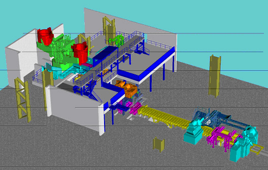
Jack-Up rigs:
Unlike barges, which is suitable for near shore operation with calm weather, the jack-up rigs can operate in harsh weather conditions in violate sea. The high tech rigs in a triangle shaped hull, supported by three legs can move up and down depending on water level in the sea. Due to stable mooring facility, they can operate at high speed to a depth of 8000m. Like barge, they are not self-propellant.
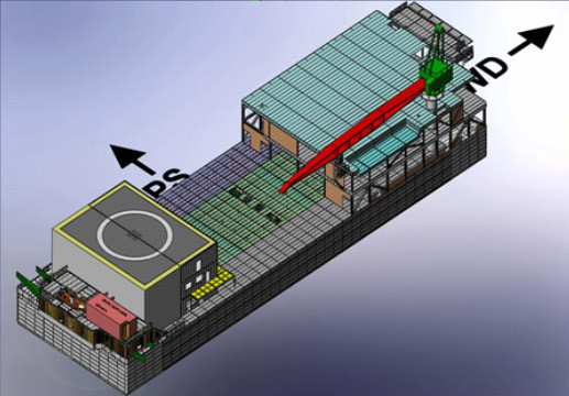
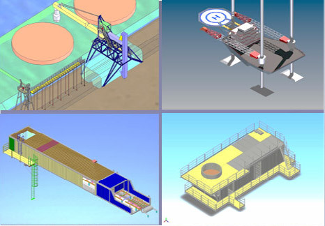
Jack-up rigs contain the following system/equipment:
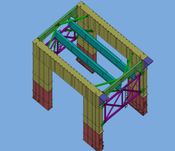
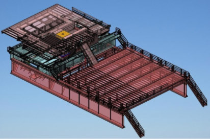
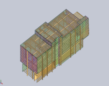
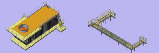
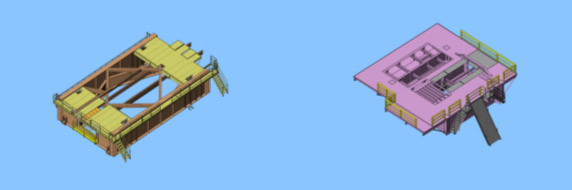
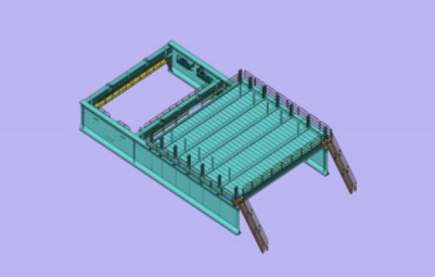
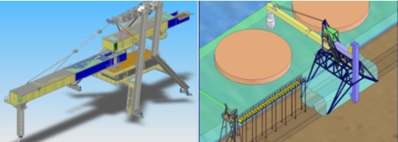
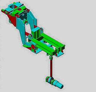
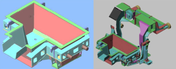
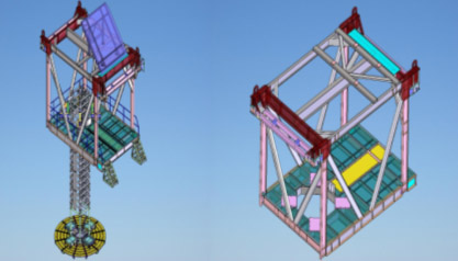
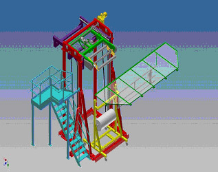
- Drilling platform supported by the cantilever structure on movable substructure,
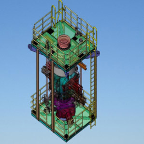
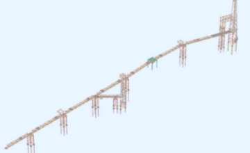
- Derrick structure along with draw works,
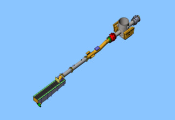
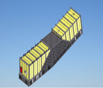
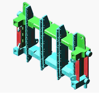
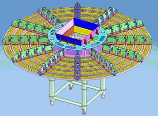
- Pipe handling system,
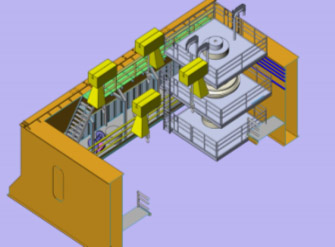
- Power plant,
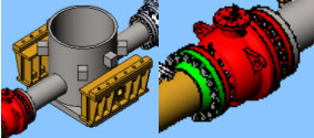
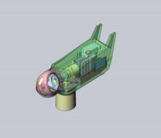
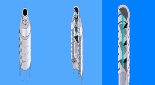
- BOP Equipment: diverter, stack and control system,
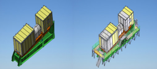
- Mud handling and Treatment,
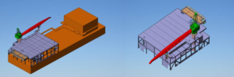
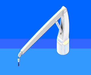
- Cranes,
- Storage area to handle bulk material like cement, drilling water, fuel for generator and Mud tanks,
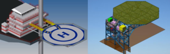
- Accommodations for Staff: normally for over 100 persons,
- Helideck on cantilever structure.
- Jack-up facility up to 200m